 English
 日本語
日本語 العربية
 French
 Deutsch
 Español
 Portuguese
 Русский
 Bahasa Indonesia
 中文
中文Strictly based on current national and industry standards, the principles of structural mechanics and engineering technical requirements, this article provides an objective, purely technical review and well-intentioned risk warnings. It aims to help the industry optimize construction workmanship, avoid engineering hazards and promote compliant standardization. The whole text is intended only as technical exchange and a reference for industry improvement, with no subjective direction and not aimed at anyone.
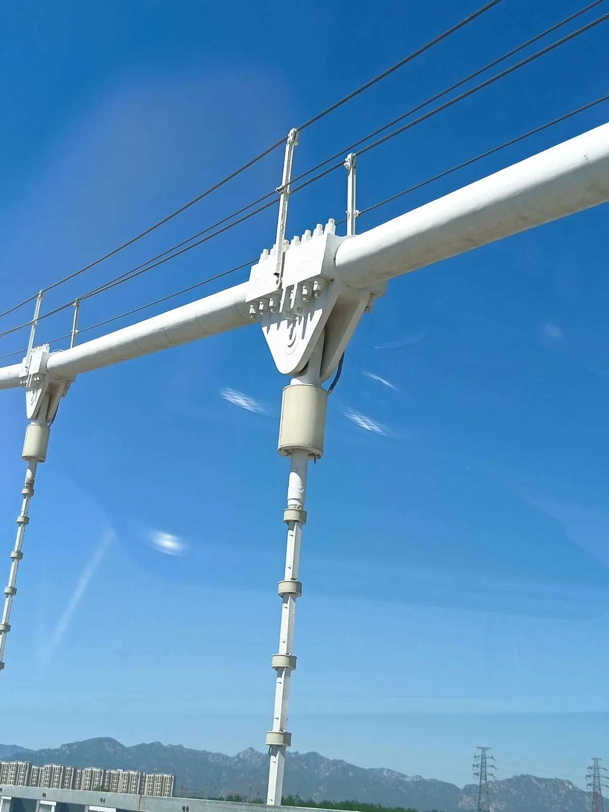
I. Core risk warning: the U-bolt joint has an inherent structural shortcoming, with collapse risk within a dozen or so years
In the design and construction of long-span flexible brackets above 32 metres, the simple connection of a conventional U-bolt directly clamping the stranded cable is a traditional, non-standard, outdated construction.
Judged by long-term engineering O&M and structural safety practice, this structure falls completely short of the 25-year service standard of PV plants; in fact, after about 10 years of operation, wire breaks and structural instability can very easily appear, triggering large-scale serious collapse accidents. This outdated structure is completely unsuited to the complex outdoor conditions of long spans, high wind pressure and frequent alternating dynamic loads.
Based on many years of front-line structural R&D and engineering practice, we fully eliminated the outdated U-bolt clamping joint technique as early as the 2016 round of project technical iteration. Over the years we have continued to deepen the optimization of long-span flexible bracket joints and accumulated a number of original, mature patented technical schemes, which can thoroughly solve the inherent defects of this type of traditional design at the structural root and provide a mature, implementable reference for the standardization and long-term safety of industry joints.
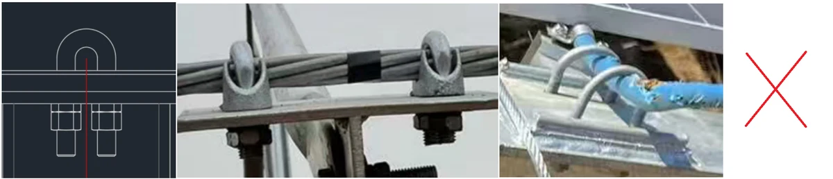
Combining the principles of structural mechanics, measured section data and actual engineering feedback, this outdated joint has three inherent shortcoming that cannot be repaired later — in particular the severe insufficiency of contact area, which is far more dangerous than generally recognized in the industry:
1. Extremely small compressive contact area: nominal point contact, with pressure far exceeding limits
Analysis of measured engineering section data shows: the U-bolt and the stranded cable are in essence in pure point contact, not the line contact the industry mistakenly assumes. The actual effective compressive section area at a single clamping position is no more than 6 square millimetres. Compared with the full-area surface contact structure of a proper cable clamp 90 millimetres long, the effective contact area and strength of a U-bolt are less than 1% of the standard compliant contact area.
The extremely small bearing area causes an eruption of local stress concentration. Under years of tension, alternating wind vibration loads and repeated action, the local pressure is severely excessive over the long term, continuously squeezing and wearing the galvanized layer of the outer wires of the strand and directly destroying the anti-corrosion coating. Especially in the C5 highly corrosive coastal environment, cable corrosion, wire breaks and weakening of the strand appear quickly, laying an irreversible and major safety hazard for later structural failure.
2. Insufficient clamping friction stability: a long-term hidden danger of slip and loosening
This simple joint has no fully enveloping, uniformly clamping structure, and the friction coefficient of the contact surface is extremely low. Affected by seasonal temperature deformation, daily wind vibration and fluctuating operating loads, the strand is very prone to micro-slip and loosening offset, gradually causing continuous decay of the bracket's pretension force and imbalance of the overall load-bearing system, with structural stability declining rapidly year by year.
3. Weak fatigue performance, unsuited to long-term outdoor service
A PV bracket is a structure that bears high-frequency wind vibration fatigue loads around the clock, placing extremely high demands on joint toughness, anti-loosening capability and fatigue resistance. The simple U-bolt joint has no special fatigue performance and its contact form is extremely unreasonable; after long-term operation, loosening and complete failure of the clamp occur easily, and its durability falls far short of the long-term O&M standards of PV plants.
II. The regulatory red line is clear: traditional clamping workmanship no longer complies with current national and industry standards
A number of current national and industry standards have set hard requirements for the clamping method of cable structures, load-bearing requirements, and anti-slip and fatigue performance, and the conventional U-bolt point-clamping technique does not match these compliance requirements at all.
1. T/CPIA 0047-2022 Technical Guidelines for the Design and Installation of PV Flexible Brackets, Article 5.4
Cable clamps must adopt surface-contact clamping workmanship; point contact and line contact fixing are strictly prohibited; to avoid cable crushing, wear and stress concentration, the joint must meet the 25-year durability, anti-loosening and anti-fatigue design requirements.
2. NB/T 11813-2025 Technical Specification for Cable-Structure PV Brackets, Article 5.3.3
Cable clamps must not slip; the clamping friction force must exceed the ultimate cable force difference; under 1.1 times the design cable force, slip must be ≤ 0.1 mm; the joint must pass anti-slip and 2-million-cycle fatigue tests; full-circumference surface-contact, uniformly loaded cable clamps are required, and simple point-contact fixing is prohibited.
3. GB/T 35694 Code for the Support Structure of PV Power Stations
The cable anchoring structure must transfer force reliably without damaging the strand, and must eliminate slip, loosening and stress concentration damage; the joint's life must match the plant's 25-year safe operation standard.
4. JGJ 257 Technical Specification for Cable Structures
Cable fittings must be fixed with dedicated standardized components, ensuring full-area surface contact and uniform loading; point-contact and line-contact simple fixing techniques are prohibited.
An objective technical summary: clamping the stranded cable with an ordinary U-bolt is a non-standard, non-compliant, simple, outdated construction. With only 6 square millimetres of contact area — less than 1% of the compliant area — this extreme structural defect means its structural safety, mechanical stability and long-term durability all fail to meet the engineering application standards of long-span flexible brackets above 32 metres.
III. Suggestions for industry optimization: refine dedicated long-span standards to help the whole industry upgrade quality
Considering the particular working conditions of ultra-long-span flexible brackets and the detail gaps in the implementation of current industry codes, we sincerely suggest that the industry further refine special technical rules.

Focusing on long-span scenarios above 32 metres, specify the minimum effective clamping contact area, the surface-contact enveloping length and the local stress control threshold; improve the dedicated cable clamp structure standard, anti-slip parameter thresholds, fatigue test criteria and cable protection workmanship requirements. In this way the design, material selection, construction and acceptance of long-span flexible brackets will all have precise, implementable standardization bases, helping each project avoid safety hazards at the source, reduce later O&M risks, and pushing the standardized upgrading of the whole flexible bracket industry.
IV. Suggestions for engineering implementation: optimize tendering and acceptance standards to avoid long-term hazards at the source
To help all projects achieve smooth, compliant delivery and long-term, stable and safe operation, we suggest optimizing the review focus at tender evaluation, material entry acceptance and completion acceptance, concentrating on physical workmanship and verifiable hard indicators:
1. Appropriately reduce the weight given to theoretical written schemes, and focus on verifying the physical construction of core joints, the clamping contact form and the measured contact area;
2. Set surface-contact cable clamp structures, uniformly loaded construction, anti-slip design and anti-fatigue workmanship as core technical conditions for project admission;
3. Include core joint construction, cable fitting specifications, clamping enveloping length and contact-surface workmanship details in entry verification and as mandatory completion inspection items;
4. Gradually replace the simple non-standard clamping technique at the procurement and construction stages, and put an end to dangerous joint constructions with millimetre-scale contact areas, making the bracket structure more standardized, more stable and more durable.
Through front-loaded quality control and refined acceptance, risks in the middle and later stages — loosening, slip, failure and collapse — can be avoided to the greatest extent, guaranteeing safe and stable operation over the whole life cycle of the plant.
V. A compliant, mature optimized scheme: patented standardized joints that eradicate the structural hazard
For the industry-wide common problems of long-span brackets — too small a contact area, stress concentration, slip and loosening, insufficient fatigue durability — and drawing on our years of technical iteration experience and a complete set of patented technologies, there are now mature standardized solutions fully aligned with current national and industry standards, which can perfectly replace the traditional simple U-bolt joint and adapt to all long-span, high-wind-pressure complex conditions.
The scheme adopts a dedicated full-circumference surface-contact cable clamp, a full-area enveloping uniformly loaded structure, professional anti-loosening locking design and tensioning matching workmanship dedicated to long spans, achieving three core structural upgrades:
1. Full-area surface contact with uniform loading, completely eliminating point stress concentration, effectively protecting the strand and its anti-corrosion layer, and eradicating cable wear, corrosion and wire breaks at the root;
2. Clamping friction fully up to standard, completely avoiding slip, loosening and pretension decay caused by wind vibration, load fluctuation and temperature deformation, and guaranteeing long-term balance and stability of the structural load-bearing system;
3. Joint fatigue and ageing resistance fully meeting the 25-year service requirement of the standards, thoroughly solving the industry pain points of insufficient joint life and collapse within about ten years.
Technical conclusion
The core lifeline of the long-term safe operation of long-span flexible brackets lies in the workmanship compliance and structural reliability of the core connecting joints.
The traditional U-bolt clamping construction — nominal point contact, a compressive area of less than 6 square millimetres, only about 1% of the compliant area — is an extremely dangerous and unreasonable structure. It not only fails to meet the 25-year service standard, but carries a serious risk of bracket collapse after about ten years of operation.
The core of the industry's technical iteration is to eliminate backward non-standard workmanship and promote compliant, standardized structures. We hope that by sharing technical experience we can lead the industry to value joint details, follow codes and standards, and upgrade structural workmanship, avoiding engineering safety hazards at the source and jointly pushing the field of long-span flexible brackets onto a high-quality development path that is safer, more standardized, longer-lasting and more compliant.