 English
 日本語
日本語 العربية
 French
 Deutsch
 Español
 Portuguese
 Русский
 Bahasa Indonesia
 中文
中文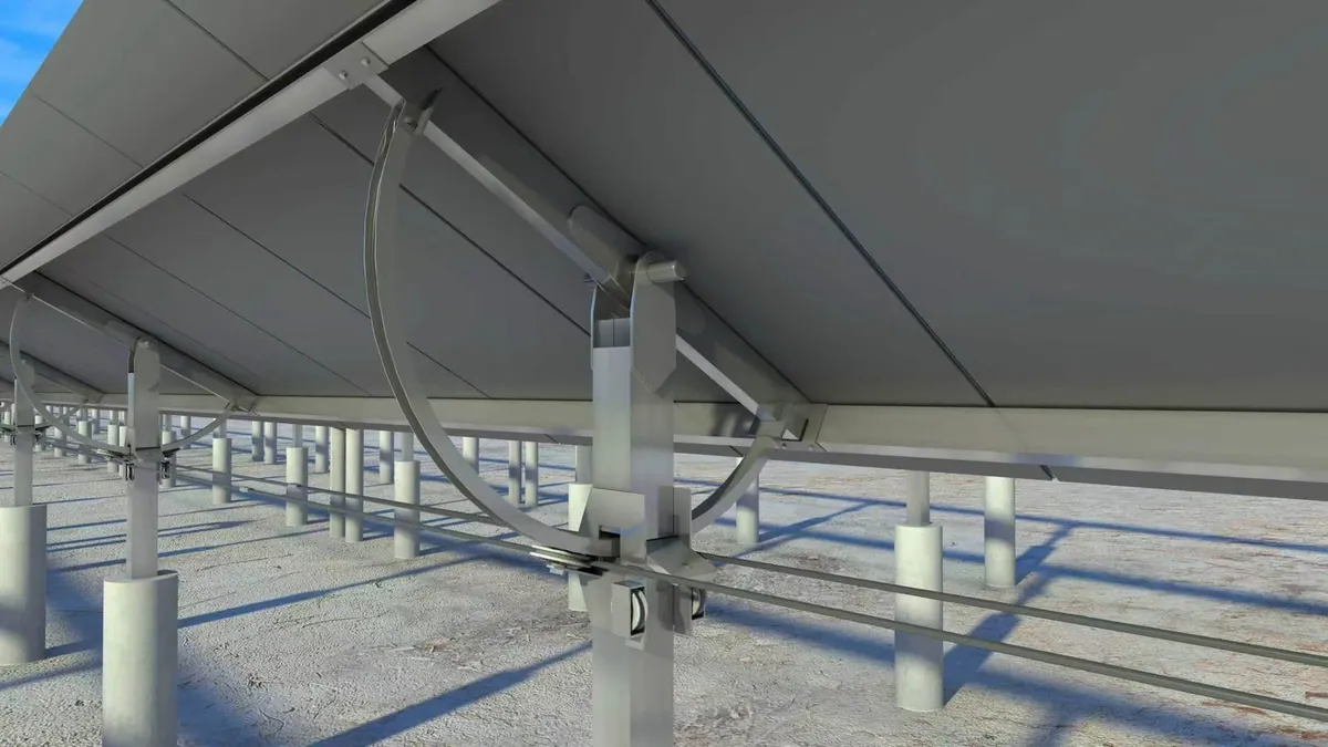
This article draws on national policies, standards and codes, the current state of the industry and public data to carry out an objective technical discussion. Its aim is to make flexible bracket structures sounder and national assets safer; it is not directed at anyone.
Structural upgrading of long-span flexible brackets: consolidating the engineering safety baseline and enabling high-quality development of the PV industry
Introduction: Based on the actual conditions of windy regions across the country, this article focuses on the core subjects of structural safety and long-term stability of long-span flexible brackets. From professional dimensions including mechanical principles, current national and industry standards, and industrial practice, it analyses in depth the core value of sound structural design, provides owners, design institutes, bracket manufacturers and industry professionals with implementable safety technical schemes, helps improve the whole-life-cycle operating benefits of PV plants, and safeguards national energy assets.
I. Technical upgrading of long-span flexible brackets: anchoring on mechanical principles to consolidate the safety foundation of plants
As an innovative application scheme in the PV industry, PV long-span flexible brackets (32 m–70 m) have been widely used in various PV projects thanks to their site adaptability. The product belongs to a flexible load-bearing cable system, with structural characteristics of a small self-damping coefficient and high sensitivity to wind load. Southeast coastal high-wind-pressure regions and frequently gusty regions such as Xinjiang and Inner Mongolia in the northwest impose extremely high technical requirements on the wind resistance and stability of bracket structures, and these are also the core direction of the industry's technical upgrading.
From the core principles of engineering mechanics, the spacing of suspended trusses is a key parameter of structural stability: in low-wind regions with wind pressure below 0.4 kN/m², the reasonable spacing of suspended trusses should not exceed 6 metres; in strong-wind regions such as the southeast coast and the northwest, to ensure foundation stability and balanced load transfer, the truss spacing must be strictly controlled within 3–4 metres — this is the baseline technical standard for the long-term operation of brackets.
At present, the industry is upgrading rapidly towards standardization. Quality technical schemes strictly follow GB 50009-2023 Load Code for the Design of Building Structures and the NB/T 11813-2025 industry standard, complete special verification of wind-induced vibration response and negative wind pressure stability, and abandon wishful thinking in design. On the basis of scientific mechanical calculation and in strict compliance with normative spacing design standards, they avoid wind-induced sway, structural instability and other safety hazards at the source, effectively guarantee plant operation safety, and prevent losses to national assets and project investment.
II. The same mechanical logic: drawing on proven engineering experience to optimize flexible bracket technical schemes
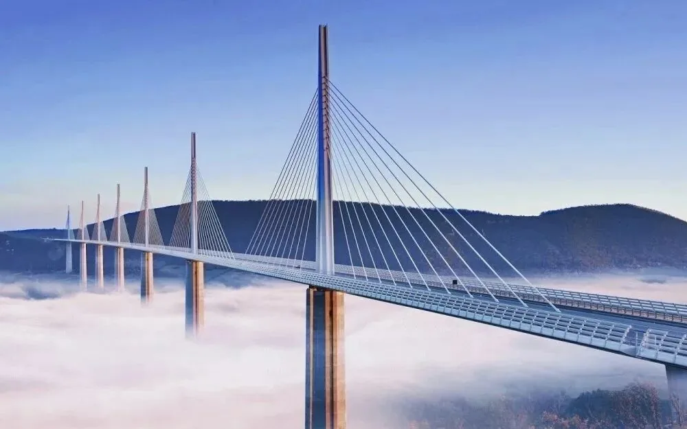
PV long-span flexible brackets of 32 m–70 m belong, like long-span cable-stayed bridges and suspension bridges, to flexible cable-supported spatial structural systems. The two share the same origins in structural mechanics, elasticity and wind engineering theory, and their load-transfer mechanisms and stability control logic are highly consistent, differing only in application scenarios and load parameters. Drawing on the mechanical principles proven over a century of bridge engineering is the core path for the technical upgrading of PV flexible brackets.
The core load-bearing elements of the two correspond professionally, which provides a clear direction for technical optimization:
1. The bridge deck system corresponds to the main load-bearing cables of the flexible bracket plus the PV module array. As the core load-bearing component, its connection reliability and overall stiffness directly determine the operational stability of the structure;
2. The stay cables / suspension hangers of a bridge correspond to the suspended trusses of the flexible bracket. As the core components for wind vibration suppression and load distribution, their uniform spacing is key to structural stability and can effectively avoid wind-induced resonance and local load concentration;
3. The main cable of a suspension bridge corresponds to the main load-bearing cable of the flexible bracket. As the core force-transfer component, it carries the core load-transfer function and is the fundamental basis of structural safety.
Relying on proven engineering mechanics experience and strictly controlling the layout standards of load-bearing members is the core technical guarantee for the long-term stability of long-span flexible brackets and for extending their service life.
III. Core safety technical scheme: multi-directional stabilizing stranded-cable system safeguarding the whole life cycle of the plant
For extreme wind conditions in all regions of the country, long-span flexible brackets of 32 m–70 m need to be equipped with professional wind-resistant stabilization technology. This is a hard prerequisite for meeting the verification requirements of national and industry standards and guaranteeing 25 years of safe plant operation, and it is also the core standard configuration of quality technology in the industry.
The invention patent — the multi-directional stabilizing stranded-cable system — is a mature wind-resistant stabilization technology with three irreplaceable core advantages, empowering plant safety and benefits simultaneously:
1. Strong resistance to negative wind pressure: it can effectively withstand the vertical suction caused by typhoons and strong winds, completely solving the uplift and sway problems of long-span brackets under strong winds, and fully meeting the negative wind pressure stability verification requirements of national standards;
2. Precise suppression of wind vibration and air turbulence: it comprehensively suppresses vortex-induced vibration, flutter, buffeting and other wind-induced vibrations as well as air turbulence damage, reduces resonance peaks, constrains structural displacement, and comprehensively improves the wind reliability of the structure;
3. Improved structural stiffness: it reinforces the cable-supported system in all dimensions, allowing the flexible structure to achieve rigid stability. It serves as the last line of defence for the safe operation of long-span flexible brackets, and greatly reduces plant O&M costs and safety risks.
This technical scheme is the core configuration for the safe deployment and long-term operation of long-span flexible brackets. It can reduce engineering hazards at the root, ensure stable power generation revenue, and protect national energy assets to the greatest extent.
IV. Industry development and implementation suggestions
(1) Standards empowering the standardized development of the industry
With the industry's technology iterating rapidly, in order to further promote the high-quality development of the long-span flexible bracket industry, it is suggested to continuously improve the special safety standards system: for different spans and different wind regions, specify technical requirements such as truss spacing, wind-resistant structural configuration and special wind tunnel tests, fill the gaps in the codes, so that industry design, construction and acceptance have standards to follow, and push up the overall technical level of the industry.
(2) Owners and tendering parties strictly controlling technical quality
As the parties responsible for plant investment, project owners and tendering parties should, at the tendering stage, include core safety technologies such as negative wind pressure resistance, wind vibration control and all-dimensional stability as mandatory technical clauses; strictly review structural design drawings, mechanical calculation reports and project-specific wind tunnel test reports; and give priority to quality schemes that comply with national and industry standards, are technically mature and structurally sound, so as to control project quality at the source and safeguard investment returns and asset safety.
V. Vision for industry development
The PV industry is an important part of the national energy strategy, and plant safety directly relates to massive national energy assets and long-term investment value. The long-span flexible bracket industry must adhere to the essence of engineering, focus on technical innovation and quality upgrading, take scientific mechanical design as the core and stringent standards as the principle, and continuously optimize structural schemes and improve product safety and reliability.
May industry colleagues work hand in hand, devote themselves to technical R&D and strictly control quality, and use quality, safe and efficient flexible bracket solutions such as the multi-directional stabilizing stranded-cable system to empower the high-quality operation of PV plants, achieve the sustainable development of the industry, effectively safeguard national energy assets, and support the steady advancement of the national dual-carbon goals.
We are willing to work with owners and design institutes on prudent selection, safeguarding the peace of mind and returns of projects.