
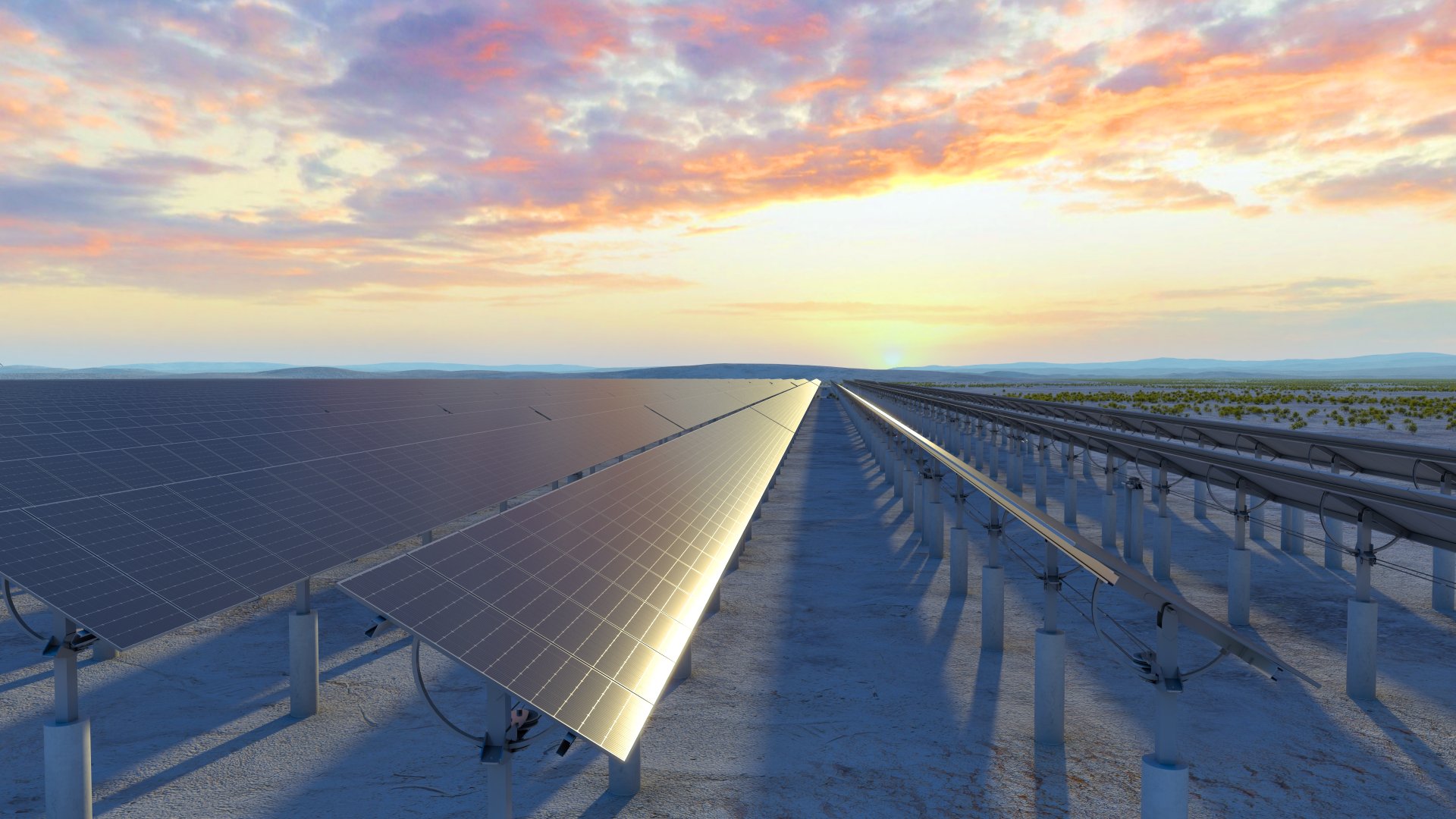
Extending the tracking array to a continuous 300–1000 m, with more than 520 modules per array, covering the same installed capacity with fewer drive units, fewer posts and fewer foundations.
| Continuous array length | 300 m to 1000 m |
|---|---|
| Modules per array | More than 520 |
| Drive density | One motor (≤180W) + one slew drive + one tracking controller for the entire array |
| Dampers and bearings | No dampers; fully bearing-free, lubrication-free hinged structure |
| Steel consumption | Approximately 40% less than conventional trackers at the same installed capacity |
| Stacking volume of split parts | Reduced by about 30%, suited to container shipping and ocean freight |
| Wind protection | AI predictive wind protection, activated at wind speeds of 30 m/s and above |
| Suitable sites | Flat sites such as level deserts, open water surfaces, tidal flats, wastewater treatment plants and coal mining subsidence areas |
| Information needed for configuration | Installed capacity, site location, ground or water surface type, wind conditions, geological conditions, planned schedule |
| Warranty | 20-year automotive-grade overall warranty (slew drive 20 years, tracking controller 15 years) |
The array length of a conventional tracker is limited by the effort arm of the drive, structural rigidity and damper configuration, so a single tracking line can only reach a limited length and requires more drive units driving separate sections. The ultra-long span PV tracker takes a different route: prestressed steel cables carry PV modules continuously along the array, while vertical posts support the array independently at each span and lock independently. A single array can be arranged continuously from 300 m to 1000 m, carrying more than 520 modules.
Behind the length is a change in drive density: an entire ultra-long array uses only one ultra-low-power motor of no more than 180W, one slew drive and one tracking controller, removing more than 90% of electrical failure points at the source.
First, lower material and logistics costs. At the same installed capacity, steel consumption is about 40% lower than conventional trackers; thanks to highly modular split design, stacking volume of split parts is reduced by about 30%, lowering container occupancy and ocean freight volume at the same time. Less steel also directly lowers embodied carbon across the project lifecycle, helping overseas projects optimize their carbon footprint and meet carbon-tariff type compliance requirements.
Second, lower failure point density. Drive units, dampers, bearings and lubrication are the main sources of failure in conventional trackers. The ultra-long span solution compresses the drive of an entire array into one motor and one slew drive, removes dampers, and adopts lubrication-free, bearing-free structures at all rotating and joint positions, significantly reducing the number of serviceable parts.
Third, simpler construction and maintenance. The product uses a split plug-in modular structure without on-site calibration, assembled by plug-in connections on site for higher installation efficiency. On the maintenance side, the slew drive corresponding to 1MW can be replaced completely by two skilled workers within one hour, with no on-site calibration or re-inspection, and the system returns to operation immediately after replacement.
The advantage of an ultra-long span rests on the premise that the array can extend continuously, so it suits large, regularly shaped and gently undulating sites best:
The flexible cable structure itself tolerates greater deformation, making it more forgiving of site unevenness than rigid brackets. However, because the array is arranged as an ultra-long continuous line, highly undulating terrain such as mountainous sites must be evaluated separately by our engineers based on span, height differences between posts and foundation conditions.
The layout of an ultra-long array requires the following conditions to be clarified before our engineers propose a specific arrangement and configuration:
One point deserves emphasis: longer is not automatically better. Array length, structural rigidity, drive torque and foundation conditions constrain one another, so the final solution is determined by our engineers together with the project conditions, avoiding any sacrifice of structural safety redundancy in pursuit of span.
Backed by the world-class PV steel industrial cluster in Tianjin, the company achieves an annual delivery capacity above 30GW and has the strength to deliver large-scale global clean energy plants, supporting batch supply and scheduled delivery for large centralized PV projects.
Before mass production, owners, supervisors and EPC teams may witness the accelerated marathon fatigue testing of the complete tracker on site, verifying structural fatigue, cyclic loads and extreme-condition performance equivalent to a full 25-year service life. The company-built century-equivalent weathering test system and structural safety validation carried out with universities complete the pre-delivery verification chain. The product carries a 20-year automotive-grade overall warranty, with a 20-year warranty on the slew drive and a 15-year warranty on the tracking controller.
Provide your installed capacity, site location, ground or water surface type, wind and geological conditions and planned schedule, and we will reply with a configuration recommendation and quotation within one business day.
Copyright © 2026 Tianjin Aqini New Energy Technology Co., Ltd.. All rights reserved Sitemap
 English
 日本語
日本語 العربية
 French
 Deutsch
 Español
 Portuguese
 Русский
 Bahasa Indonesia
 中文
中文