Rebuilding the load-bearing system of a PV tracking bracket on suspension-bridge design principles: cables carry the modules, vertical posts support the array at multiple points and lock independently, removing the mechanical causes of vibration, wear and fatigue from the structure.
| Load-bearing system | Prestressed steel cables carry PV modules continuously along the array, with vertical posts supporting at each span |
|---|---|
| Rotational stability | Independent locking on each vertical post builds overall rigidity; no dampers are used |
| Joints | Bearing-free, lubrication-free hinged structure; no grease maintenance at any rotating or joint position |
| Drive | One motor (≤180W) + one slew drive + one tracking controller for the entire line |
| Continuous array length | 300 m to 1000 m, with more than 520 modules per array |
| Steel consumption | Approximately 40% less than conventional trackers at the same installed capacity |
| Stacking volume of split parts | Reduced by about 30%, cutting container and ocean freight volume |
| Matching products | Ground anchors and steel strands produced in-house by the company |
| Corrosion protection and foundations | Designed specifically for the corrosion environment and geological conditions of each project |
| Structural validation | Accelerated marathon fatigue testing of the complete tracker (equivalent to a full 25-year service life) plus a century-equivalent weathering test system |
| Warranty | 20-year automotive-grade overall warranty (slew drive 20 years, tracking controller 15 years) |
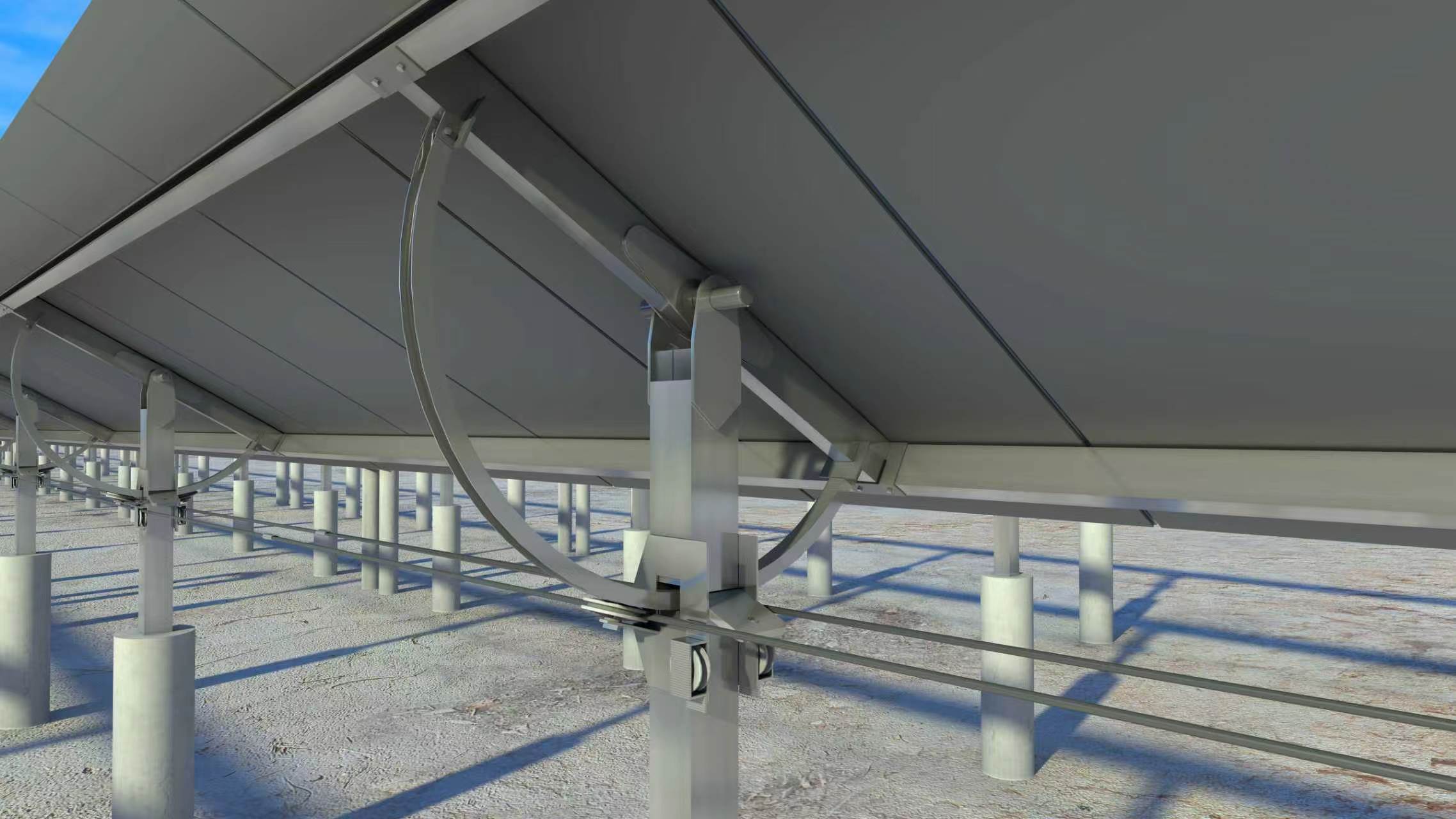
The load-bearing system of the cable-supported PV tracking bracket consists of three parts: prestressed steel cables arranged continuously along the array, vertical posts supporting the array independently at each span, and hinged nodes that carry rotation and locking functions.
PV modules are fixed directly to the cables. Module self-weight and wind loads are first transmitted continuously along the cables in the longitudinal direction, then distributed to the foundations through the vertical posts. Because the cables can extend continuously along the array, a single tracking line can reach hundreds of meters in length without additional drive points — this is the structural basis that distinguishes it from conventional rigid brackets.
The matching ground anchors and steel strands are produced in-house. Cables, anchorages and tensioning schemes are designed together according to project conditions, avoiding the interface problems that arise when the main structure and the cable assembly are supplied separately by different manufacturers.
On conventional trackers, dampers suppress wind-induced vibration — in essence a remedy for a structure that cannot contain vibration on its own. Dampers are themselves wear parts: aging, leakage and failure create long-term safety hazards, and maintenance and replacement costs accumulate over the operating life of the plant.
The cable-supported PV tracking bracket uses no dampers. Instead, every vertical post locks its rotating joint independently, so overall rigidity is established by the structure itself. Vibration is constrained by the structural system rather than dissipated by an external damping element.
As a result, a component that must be maintained continuously — and whose failure directly affects safety — is deleted from the design. Structural safety no longer depends on the continuing effectiveness of a wear part.
Conventional trackers use sliding or rolling bearings at a large number of rotating and joint positions, requiring continuous grease lubrication. Once lubrication stops or the grease ages, bearings suffer corrosion, jamming, abrasion and abnormal noise, becoming a common source of failure during plant operation.
At every rotating and joint position, the cable-supported PV tracking bracket discards conventional sliding or rolling bearings and adopts a lubrication-free hinged structure requiring no grease maintenance. It is naturally suited to the 25-year outdoor service life of a PV plant, withstands repeated accelerated fatigue cycles, and drastically cuts lifetime maintenance work and mechanical loss.
In a conventional single-axis tracker, the relationship of the lever arms is as follows: the slew drive is a short effort arm, while the torque tube and the PV array form an extremely long load arm. When the force reverses under strong wind, the array becomes a long effort arm prying the slew drive, creating persistent oscillation and accumulated gear backlash.
At the same time, modules are mounted outside the torque tube, so a 30°–45° tracking angle generates a large eccentric secondary bending moment; strong wind further amplifies this offset loading and accelerates structural fatigue. Such problems cannot be fully resolved by dampers or wind protection, and prolonged operation leads to loosening, wear, tilting and even collapse risks.
The cable-supported structure responds by changing the lever-arm relationship and the load distribution path: steel cables carry the modules continuously along the array and transmit loads, while vertical posts support the array at multiple points within each span and lock independently. The rotating joint is no longer the only long-distance load path, and eccentric loads are distributed across the continuous cable system and the multi-post system, weakening the destructive effects of reverse-lever loading and offset loads at the mechanical source.
At the same installed capacity, the cable-supported PV tracking bracket saves approximately 40% steel consumption compared with conventional trackers and reduces the stacking volume of split parts by about 30%. The savings come from two places: first, the cable-supported system replaces a large number of bending members with continuously tensioned cables; second, the minimalist drive and rotating configuration reduces the supporting structures and foundations that follow from it.
The direct result is a simultaneous reduction in raw material procurement costs, container occupancy and ocean freight volume. Less steel also lowers embodied carbon across the project lifecycle, helping overseas projects optimize their carbon footprint and meet carbon-tariff type compliance requirements — a triple cost reduction in materials, logistics and carbon compliance.
Structural validation is carried out at two levels.
The first level is accelerated marathon fatigue testing of the complete tracker: following the type-approval standards used for mature mechanical and electrical products such as automobiles, agricultural machinery and home appliances, the complete tracker undergoes accelerated fatigue testing before mass production, verifying structural fatigue, cyclic loads and extreme-condition performance equivalent to a full 25-year service life. Owners, supervisors and EPC teams may witness the entire process on site, with public witnessed testing replacing vendor self-certification.
The second level is material and component durability validation: the company has built a world-exclusive century-equivalent weathering test system that verifies long-term durability through severe accelerated aging, and collaborates with universities and institutes on structural safety validation.
The product also carries a 20-year automotive-grade overall warranty, including a 20-year warranty on the slew drive and a 15-year warranty on the tracking controller. Specific terms are defined in the contract.
Send us your project capacity, site location, wind pressure and geological conditions, and our engineers will provide a structural configuration recommendation and a matching cable assembly solution.
Copyright © 2026 Tianjin Aqini New Energy Technology Co., Ltd.. All rights reserved Sitemap
 English
 日本語
日本語 العربية
 French
 Deutsch
 Español
 Portuguese
 Русский
 Bahasa Indonesia
 中文
中文